|
ELECTRICAL SPECIFICATIONS
|
|
Frequency Range
|
144~146MHz& 430~440 MHz
|
|
Impedance
|
50Ω
|
|
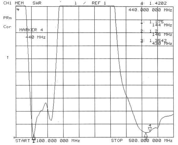
VSWR
|
<1.5
|
|
Gain
|
144~146MHz( 9.5dBi ) , 430~440 MHz ( 11.15 dBi)
|
|
Horizontal Beam Width
|
53° 144~146MHz
45° 430~440 MHz
|
|
Vertical Beam Width
|
48°144~146MHz
40°430~440 MHz
|
|
Front To Back Ratio
|
>12 dB
|
|
Lighting Protection
|
|
|
Connector Type
|
N-K(FEMALE),SO239,UHF FEMALE,SL16-K(FEMALE)
|
|
Maximum Power
|
50W
|
|
MECHANICAL SPECIFICATIONS
|
|
Dimensions (L/W)
|
1135×1045 mm
|
|
Weight
|
725g
|
|
Rated Wind Velocity
|
60 m/s
|
|
Mounting hardware
|
Ø30-Ø50 mm
|
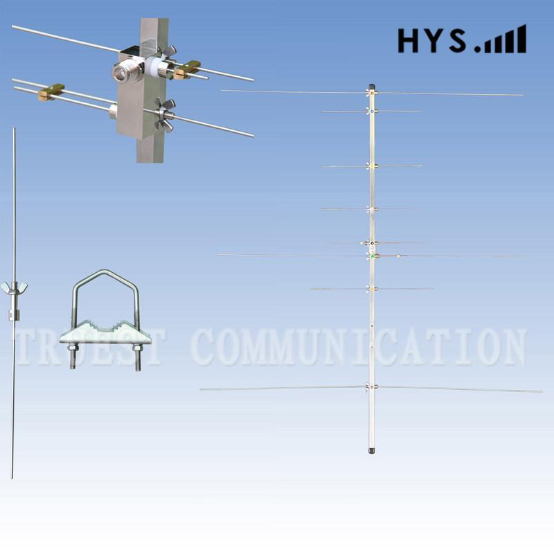
144/430MHz DUAL BAND YAGI ANTENNA
INSTRUCTION MANUAL
NOTE PLEASE READ ALL INSTRUCTIONS BEFORE ASSEMBLY
FEATURE
1. Dual band for 2m/70cm.
2. Independent element type ensures a nice gain and performance in comparison with Mono band.
3. Stainless steel boom, elements and brackets which ensures superior durability and
long performance life in all weather conditions.
4. Light weight, compact and easy to install and re-assemble.
SPECIFICATIONS
Type----------------------------- 3-Elements YAGI (145 MHz)
5-Elements YAGI (435 MHz)
Frequency---------------------- 144-146 / 430-440 MHz
Gain----------------------------- 9.5dBi / 11.15 dBi
Power input-------------------- 50 watts (FM) max.
Impedance---------------------- 50Ohm
FB ratio------------------------- more than 12dB
Boom length------------------- 1,130 mm
Connector---------------------- N Female
Suitable Mast------------------ 30 – 55 mm diameter
Weight-------------------------- 870 g
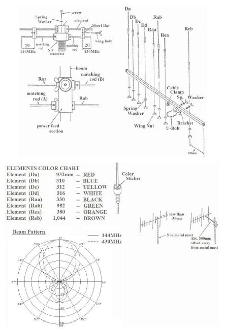
ASSEMBLING
1. Identify and arrange the 8-elements and the power feed unit of antenna see color chart.
2. Using flat washer and wing nut join each element and the power feed unit(with Raa and Rab)
according to color code to boom.
3. Insert matching rod A & B into power feed unit.
A(longer bar) should be in the hole farthest from the N female connector. B(shorter bar) should be
in the hole closest to N female connector. Using hex. wrench provided, tighten match rods in
power feed unit with set screws. Attach shorting bars per diagram.
4. Refer to drawing and attach cable clamp on boom forward from location of U-bolt bracket and on the same side as the power feed unit.
5. Mount antenna on mast in either horizontal or vertically(offset if necessary when using a metal
mast – see diagram).
6. Attach coax with N male connector to power feed unit and insert coax into clamp. Use electrical
tape or wire ties to secure coax along boom.
VSWR ADJUSTMENT
1. Adjust VSWR at center frequency of each band. Move shorting bar further from connector to
raise center frequency where VSWR is optimum.
2. Be sure wing nut assembly is tighened on the shorting bar.